-
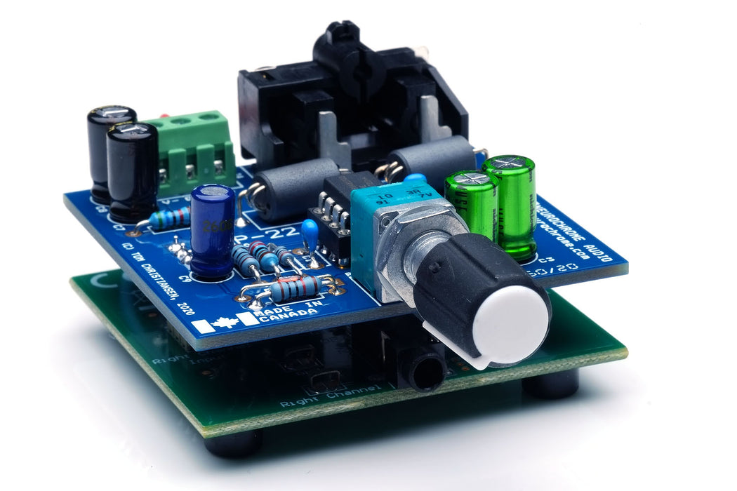
The HP-22 circuit and PCB have been optimized for performance while keeping the circuit easy to assemble. The HP-22 installs as a shield atop the OPA1622 evaluation module from Texas Instruments to provide an ultra compact, high-performance headphone amp.
The HP-22 is intended for use with the Neurochrome Preamp Power Supply, but can be powered by any power supply in the range of ±7 – ±17 V. It can even be powered by a pair of 9 V batteries in a portable headphone amp.
-
Key features of the HP-22:
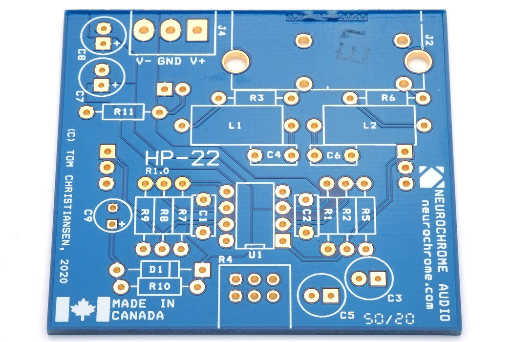
- 2-layer PCB fully optimized for performance while being easy to assemble.
- Output power: 200 mW (32 Ω), 360 mW (50 Ω), 200 mW (300 Ω) at vanishingly low distortion.
- Inputs: On-board RCA connectors.
- Alps RK097-series volume potentiometer.
- +10 dB fixed gain.
- Intended for use with a ±12 V power supply, such as the Neurochrome Preamp Power Supply.
- The PCB features elaborate use of planes and copper pours to maximize circuit performance by minimizing supply and ground impedances.
- On-board EMI/RFI input filter to prevent wifi and switch transients from interfering with the sound reproduction.
- The HP-22 is all through-hole construction with one socketed IC and is easy to solder.
- Bill-of-materials includes a Mouser Electronics Project Link for ease of parts ordering.
- Gold plated PCB, fully electrically tested by the manufacturer.
- PCB is designed and manufactured in Canada.
Build budget: The total parts cost for the HP-22 PCB is just shy of $50, including the cost of the TI OPA1622 evaluation module.
-
The full specifications of the HP-22 are tabulated below. These values were measured with the HP-22 powered by a ±12 V Neurochrome Preamp Power Supply.
| Parameter |
Value |
Notes |
| Recommended Power Supply |
±7 – ±17 V
Min. 200 mA
|
|
Idle Current Consumption
|
15 mA
20.4 mA
|
Typical
Maximum
|
| Output Power |
200 mW |
300 Ω, < 0.01 % THD+N |
| Output Power |
360 mW |
50 Ω, < 0.01 % THD+N |
| Output Power |
200 mW |
32 Ω, < 0.01 % THD+N |
| THD |
0.00003 %
(-130 dB)
|
100 mW, 32 Ω, 1 kHz |
| THD+N |
< 0.00024%
(< -112 dB)
|
180 mW, 300 Ω, 1 kHz |
| THD+N |
0.00034%
(-109 dB)
|
140 mW, 32 Ω, 1 kHz |
| THD+N |
< 0.0005%
(< -106 dB)
|
100 mW, 20 Ω, 1 kHz |
| IMD: SMPTE 60 Hz + 7 kHz @ 4:1 |
-107 dB |
100 mW, 300 Ω |
| IMD: DFD 18 kHz + 19 kHz @ 1:1 |
-115 dB |
100 mW, 300 Ω |
| IMD: DFD 917 Hz + 5.5 kHz @ 1:1 |
-110 dB |
1 mW, 300 Ω |
| Multi-Tone IMD Residual |
< -146 dB
Ref.: 100 mW
|
AP 32-tone, 100 mW, 300 Ω |
| Gain |
10 dB |
|
| Gain Flatness |
±0.015 dB |
20 Hz - 20 kHz |
| Input Sensitivity |
1.74 V RMS
570 mV RMS
|
100 mW, 300 Ω
100 mW, 32 Ω
|
| Bandwidth |
1 Hz – 1 MHz
|
100 mW, 300 Ω, -3 dB |
| Slew Rate |
±10 V/µs |
300 Ω || 220 pF load |
| Total Integrated Noise and Residual Mains Hum |
2.0 µV RMS |
20 Hz - 20 kHz, A-weighted |
| Total Integrated Noise and Residual Mains Hum |
2.6 µV RMS |
20 Hz - 20 kHz, Unweighted |
| Output DC Offset Voltage |
±400 µV (typ.)
±3.0 mV (max.)
|
Guaranteed by design
|
| Dynamic Range (AES17) |
127 dB |
1 kHz |
| Channel Separation |
90 dB |
20 Hz - 20 kHz |
| Output Impedance |
16 mΩ |
20 Hz - 20 kHz |
| PCB footprint |
51 × 55 mm |
|
| Fully assembled dimensions |
55 × 85 × 30 mm
50 g
|
(W × D × H)
|
Sound Quality
I designed the HP-22 to be sonically transparent and firmly believe I have achieved that goal. I generally prefer precise amplifiers as they render the source material naturally, without any colouration, and offer a spacious and realistic sound stage.
-
The HP-22 circuit consists of an input EMI/RFI filter followed by a volume control and a gain stage. The output is provided by an OPA1622.
The block diagram for the HP-22 is shown below.

The EMI/RFI filter prevents RF signals from nearby cellphones, wifi, as well as switch transients from interfering with the audio reproduction.
The volume is controlled by an Alps RK097 potentiometer. Those who wish to use other volume control solutions can connect them directly to the HP-22 PCB with short wires.
The enable signal to the OPA1622 is controlled to minimize turn-on and turn-off clicks and pops.
While the HP-22 provides excellent performance when built according to the instructions, many DIY audio enthusiasts enjoy tweaking circuits. Circuit tweakers will be delighted to know that the HP-22 offers great flexibility in opamp selection. As such, the LME49720 used in the input stage can easily be replaced by your favourite opamp, including discrete opamps, should you so desire.
Thus, the HP-22 caters both to those who prefer a "build it once and be done" approach and those who enjoy circuit modifications.
-
The graph below shows the THD+N vs output power for 300 Ω load. The amplifier was powered by a Neurochrome Preamp Power Supply during the measurement. The amplifier delivers 200 mW at the onset of clipping. Note that the sharp jumps (aside from when the amplifier clips) are caused by range switching in the APx525. The THD+N vs output power plots mostly show the THD+N floor of the measurement system.

Repeating the measurement with 32 Ω, respectively, reveals:

The onset of clipping occurs at 200 mW into 32 Ω.
The THD+N vs frequency plots for 100 mW into 300 Ω is shown below. Note that the measurement bandwidth was changed to 60 kHz to capture at least three harmonics of 20 kHz. This also increases the noise bandwidth, hence the THD+N, of the measurement.

Siegfried Linkwitz argues that the 1 kHz + 5.5 kHz intermodulation distortion (IMD) measurement is one of the measurements which is more indicative of the perceived sound quality. He bases this argument on the fact that IMD products in this measurement fall in the frequency range where the ear is the most sensitive (see the Fletcher-Munson curves for more detail). I think this argument carries a good amount of weight, so I measured the HP-22 accordingly. The measurement is shown below. Note that due to a limitation in the DFD IMD source of the APx525, the frequencies used must be an integer multiple of each other. Thus, I measured at 917 Hz (5500/6) + 5.5 kHz. I performed this measurement at 1.0 mW. The result is shown below.

The more conventional IMD measurements are shown below. The two plots show the SMPTE (60 Hz + 7 kHz @ 4:1) IMD and DFD (18 kHz + 19 kHz @ 1:1) IMD, respectively. Poor SMPTE IMD is often indicative of thermal issues or power supply issues in the amp. The 18k+19k IMD is indicative of the loop gain available in the amp near the end of the audible spectrum, which can be telling of an amplifier's sound quality. The HP-22 provides excellent performance on both of these measurements.


Audio Precision has developed a multi-tone test signal, which contains 32 tones from 15 Hz to 20 kHz, logarithmically spaced in frequency. This test signal sounds a bit like an out-of-tune pipe organ. It is basically the closest I can get to music with a deterministic test signal. Thus, I argue that this multi-tone signal should be used in an IMD test for the best correlation between measurements and perceived sound quality. I run this test at 100 mW (which is also the 0 dB reference in the plot). Note that even the tallest IMD components are more than 144 dB below clipping level! This is likely why the HP-22 sounds transparent. This measurement shows that it does not add anything (or at least extremely little) to the source signal, even at levels just below clipping where the amplifier is working the hardest. Also note that the amplifier output is nearly free of mains-related hum or noise.

As seen in the plot below, the HP-22 shows only a tiny amount of residual mains hum.

For completeness, I measured the amplitude response and gain flatness as shown below.


The plot below shows the crosstalk between the left and right channel. The channel isolation measures nearly 100 dB mid-band and better than 90 dB at 20 kHz.

The output impedance is shown below.

Stability
Stable operation, even when presented with a reactive load, is paramount for any amplifier. This is especially true for headphone amplifiers as the headphone cable often presents nearly 1 nF of capacitance. Thus, I tested the HP-22 with capacitive load. The results are shown below.
As seen below, the transient response of the HP-22 is clean and free of ringing, even with a significant capacitive load (4.7 nF). A little bit of well-controlled ringing shows at 10 nF capacitive load. Note that this corresponds to running the HP-22 with about 100 m (~330 ft) of headphone cable attached.


Clipping Behaviour
Clean clipping behaviour is important for any amplifier. The plots below shows the output of the HP-22 just below clipping, at the onset of clipping, and when clipping hard. As seen in the plots, the HP-22 recovers cleanly from clipping and shows no signs of rail sticking or oscillation as it exits clipping.


Power-up and power-down transients
The HP-22 does not feature an output relay. Rather the output stage is enabled after a short delay following power-up. The delay was adjusted to minimize the turn-on transient. As seen is the plot below, the turn-on transient (5 seconds into the measurement) is quite low and is safe for any headphone. The turn-off transient (13.5 seconds in) is negligible.

-
The HP-22 can be turned into a desktop headphone amp as shown in the build video below.
The build shown in the video uses the drill templates and bill-of-materials provided below.