-
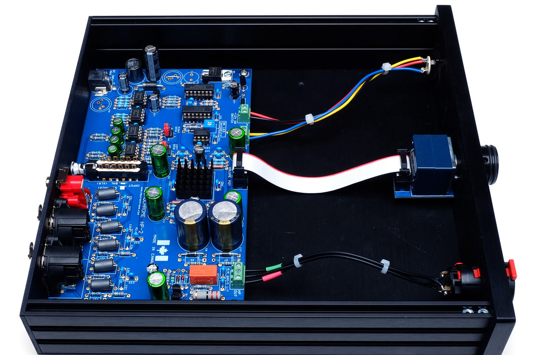
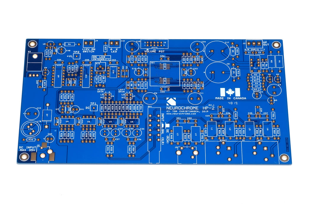
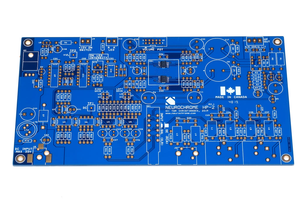
The HP-2 circuit and PCB have been optimized for performance while keeping the circuit relatively easy to assemble. As such, the HP-2 includes two surface mounted ICs (SOIC-08 package). These are quite straight-forward to solder, but for those who prefer to forego the SMD soldering, I am able to provide the PCB with these ICs pre-populated for an additional fee.
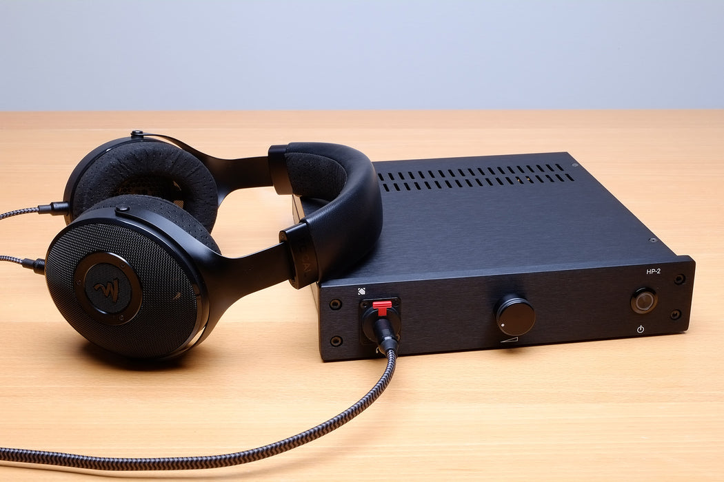
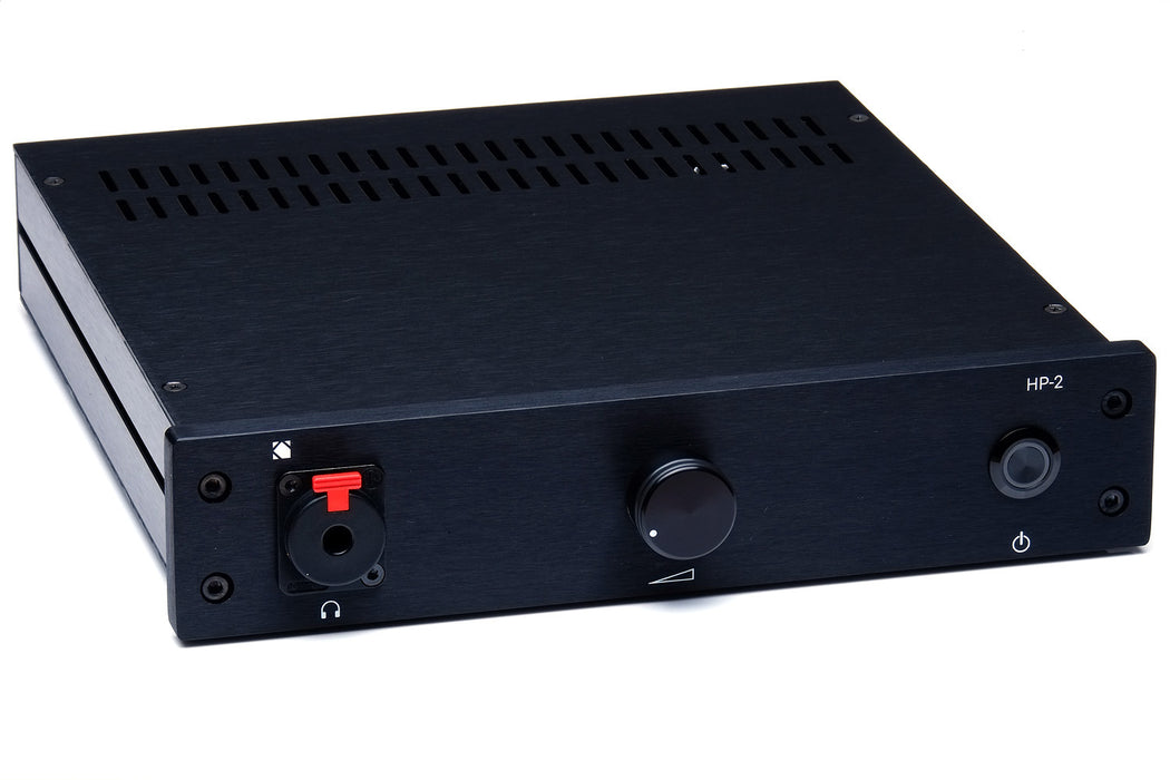
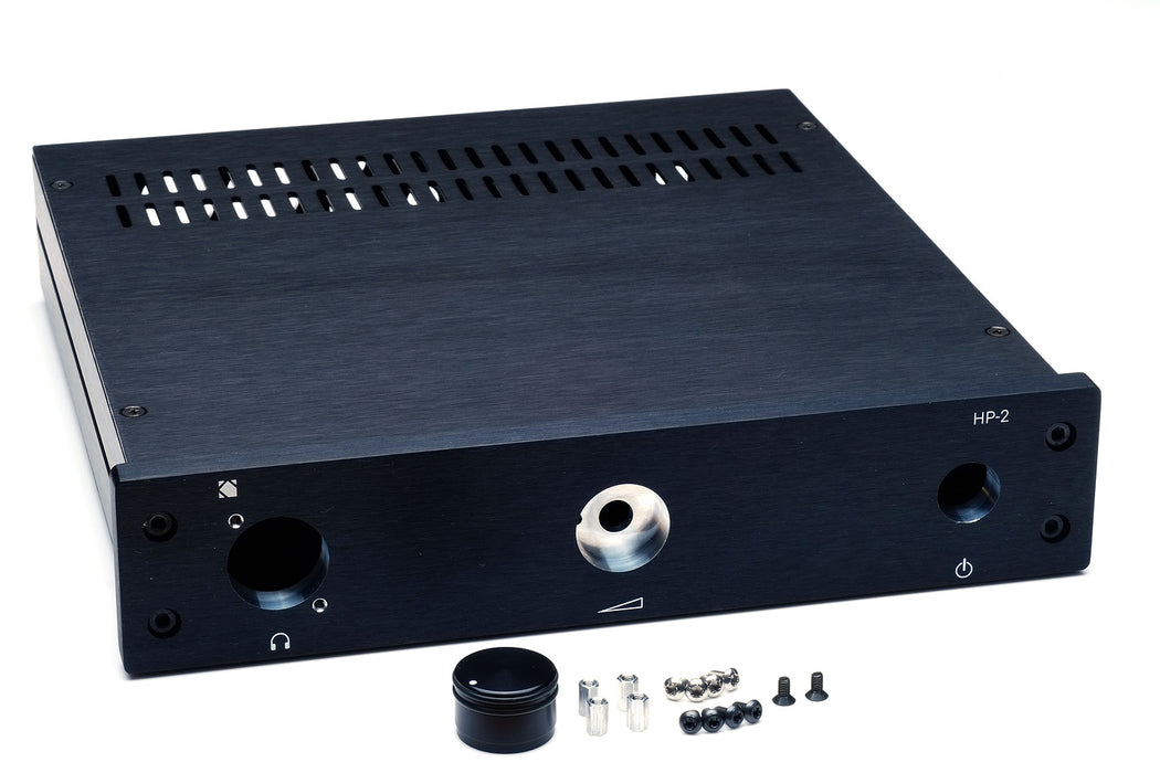
Chassis design and manufacturing is a challenge for many DIYers. Thus, I offer a nice aluminum chassis, which has been fully customized for the HP-2. This gives even mechanically challenged builders the option of showcasing their build. The chassis comes with all the hardware necessary to mount the PCB and connectors. The volume knob is included with the chassis as well.
Due to the complexity of the design, the chassis alone will set you back over $250 if you were to order it directly from the manufacturer. Thanks to the bulk discount I received when I placed my chassis order, I am able to provide it for considerably less.
-
Key features of the HP-2:
- 4-layer PCB fully optimized for performance while being relatively easy to assemble.
- Output power: 440 mW (32 Ω), 660 mW (50 Ω), 260 mW (300 Ω) at vanishingly low distortion.
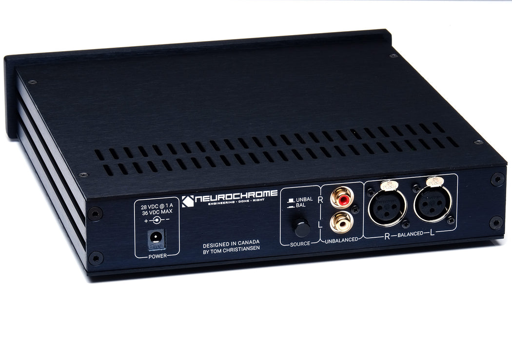
- Inputs: Balanced/differential (XLR) and unbalanced/single-ended (RCA).
- Alps "Blue Velvet" volume potentiometer.
- +5 dB and +15 dB gain settings (jumper selectable).
- Integrated headphone protection circuit, which disconnects your headphones in the case of DC voltage on the output of the amplifier.
- Integrated output muting circuit ensures that the HP-2 is absent of turn-on and turn-off clicks and pops.
- Optimized on-board RLC power supply filter allowing for stellar performance with the recommended switching power supply.
- External 28 VDC switching power supply accepting 85 – 264 VAC mains for use world wide.
- The PCB features elaborate use of planes and copper pours to maximize circuit performance by minimizing supply and ground impedances.
- On-board EMI/RFI input filter to prevent wifi and switch transients from interfering with the sound reproduction.
- With the exception of two SOIC-08 surface mounted ICs, the HP-2 is all through-hole construction with socketed ICs and is easy to solder.
- Bill-of-materials includes a Mouser Electronics Project Link for ease of parts ordering.
- Gold plated PCB, fully electrically tested by the manufacturer.
- PCB is designed and manufactured in Canada.
- Custom designed chassis manufactured in Italy.
Build budget: The total parts cost for the HP-2 PCB is approximately $145, including the desktop power supply. Should you choose to use my custom designed chassis, you will need to purchase the output connector and power switch as well, which will add $18.
-
The full set of specifications for the HP-2 are tabulated below.
| Parameter |
Value |
Notes |
| Output Power |
260 mW |
300 Ω, < 0.01 % THD+N |
| Output Power |
660 mW |
50 Ω, < 0.01 % THD+N |
| Output Power |
440 mW |
32 Ω, < 0.01 % THD+N |
| Output Power |
280 mW |
20 Ω, < 0.01 % THD+N |
| THD |
< 0.00003 %
(< -130 dB)
|
50 mW, 300 Ω, 1 kHz |
| THD |
0.00014 %
(- 117 dB)
|
50 mW, 32 Ω, 1 kHz |
| THD+N |
0.00028%
(-111 dB)
|
100 mW, 300 Ω, 1 kHz |
| IMD: SMPTE 60 Hz + 7 kHz @ 4:1 |
-109 dB |
100 mW, 300 Ω |
| IMD: DFD 18 kHz + 19 kHz @ 1:1 |
-119 dB |
100 mW, 300 Ω |
| IMD: DFD 917 Hz + 5.5 kHz @ 1:1 |
-103 dB |
1 mW, 300 Ω |
| Multi-Tone IMD Residual |
< -144 dB Ref.: 100 mW |
AP 32-tone, 100 mW, 300 Ω |
| Gain |
5.0 dB
15 dB
|
Jumper selectable, 10 mW, 300 Ω.
|
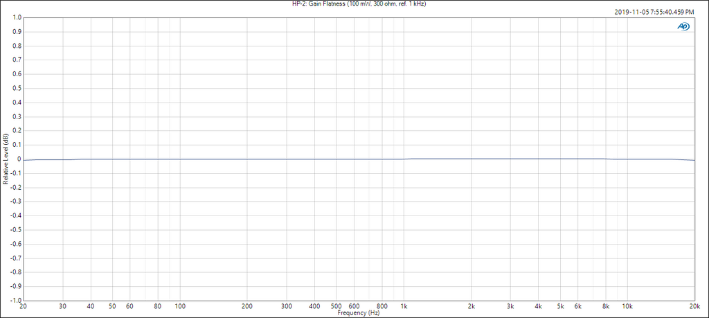
| Gain Flatness |
±0.005 dB
|
20 Hz - 20 kHz
|
| Input Sensitivity |
2.90 V RMS
865 mV RMS
|
5.5 dB gain, 100 mW, 300 Ω
16 dB gain, 100 mW, 300 Ω
|
| Bandwidth |
0.35 Hz – 290 kHz |
100 mW, 300 Ω, -3 dB |
| Slew Rate |
8.5 V/µs
|
300 Ω || 220 pF load |
| Total Integrated Noise and Residual Mains Hum |
1.0 µV RMS |
20 Hz - 20 kHz, A-weighted |
| Total Integrated Noise and Residual Mains Hum |
1.3 µV RMS |
20 Hz - 20 kHz, Unweighted |
| Output DC Offset Voltage |
0 V |
Output is AC coupled |
| Dynamic Range (AES17) |
125 dB |
1 kHz |
| Channel Separation |
78 dB |
20 Hz - 20 kHz |
| Common-Mode Rejection Ratio |
> 64 dB |
20 Hz - 20 kHz |
| Output Impedance |
2.6 Ω |
20 Hz - 20 kHz |
| PCB footprint |
110 × 190 mm |
|
| Fully assembled dimensions |
240 × 260 × 55 mm
1450 g
|
(W × D × H)
|
Sound Quality
I designed the HP-2 to be sonically transparent and firmly believe I have achieved that goal. I generally prefer precise amplifiers as they render the source material naturally, without any colouration, and offer a spacious and realistic sound stage.
-
The HP-2 circuit consists of a differential input with jumper-selectable gain. The input stage is followed by an Alps "Blue Velvet" (RK271-series) volume pot. Two OPA1656 headphone driver opamps form the output stage. The two opamps within each OPA1656 are connected in parallel for higher output power into low-impedance loads.
The block diagram for the HP-2 is shown below.
The output is AC coupled (i.e. uses an output capacitor), and nested feedback is used to cancel the distortion of the output capacitor. The result is an output stage that provides exceptionally low distortion, thus, is sonically transparent.
The input stage features an EMI/RFI input filter. This prevents RF signals from nearby cellphones, wifi, as well as switch transients from interfering with the audio reproduction.
The volume is controlled by an Alps "Blue Velvet" (RK271-series) volume potentiometer. Those who wish to use other volume control solutions will be delighted to know, that the chassis features an open area of approximately 120 × 125 mm between the amplifier PCB and the front panel.
The HP-2 has two gain options: +5 dB and +15 dB. The gain is changed by moving two jumpers on the PCB. These gains were selected to best accommodate a wide range of signal sources, ranging from professional DACs to consumer tablets and smartphones. Should you desire a different gain than the provided defaults, the gain can be changed by changing two resistors.
While the HP-2 provides excellent performance when built according to the instructions, many DIY audio enthusiasts enjoy tweaking circuits. Circuit tweakers will be delighted to know that the HP-2 offers great flexibility in opamp selection. As such, the LME49720 used in the input stage can easily be replaced by your favourite opamp, including discrete opamps, should you so desire.
Similarly, should the Alps "Blue Velvet" volume pot not suit your fancy, the chassis features plenty of room to allow for other volume control solutions.
Thus, the HP-2 caters both to those who prefer a "build it once and be done" approach and those who enjoy circuit modifications.
-
The graph below shows the THD+N vs output power for 300 Ω load. The amplifier delivers 260 mW at the onset of clipping. Note that the sharp jumps (aside from when the amplifier clips) are caused by range switching in the APx525. The THD+N vs output power plots mostly show the THD+N floor of the measurement system.

Repeating the measurement with 50 Ω and 32 Ω, respectively, reveals:


The onset of clipping occurs at 660 mW and 440 mW for 50 Ω and 32 Ω, respectively.
The distortion of the HP-2 is so low that it challenges the dynamic range of my Audio Precision APx525. Thus, I measure the THD with a precision oscillator connected to the input of the HP-2, and suppress the oscillator fundamental on the output of the HP-2 using a passive notch filter. This to circumvent the dynamic range limitations of the APx525 analyzer section. The result of the measurement is shown below for 50 mW into 300 Ω.

After compensating for the losses of the notch filter, the THD measures approximately -133 dB. I certainly feel comfortable claiming -130 dB (0.00003 %).
The THD+N vs frequency plots for 100 mW into 300 Ω is shown below. Note that the measurement bandwidth was changed to 60 kHz to capture at least three harmonics of 20 kHz. This also increases the noise bandwidth, hence the THD+N, of the measurement.

Siegfried Linkwitz argues that the 1 kHz + 5.5 kHz intermodulation distortion (IMD) measurement is one of the measurements which is more indicative of the perceived sound quality. He bases this argument on the fact that IMD products in this measurement fall in the frequency range where the ear is the most sensitive (see the Fletcher-Munson curves for more detail). I think this argument carries a good amount of weight, so I measured the HP-2 accordingly. The measurement is shown below. Note that due to a limitation in the DFD IMD source of the APx525, the frequencies used must be an integer multiple of each other. Thus, I measured at 917 Hz (5500/6) + 5.5 kHz. I performed this measurement at 1.0 mW. The result is shown below.

The more conventional IMD measurements are shown below. The two plots show the SMPTE (60 Hz + 7 kHz @ 4:1) IMD and DFD (18 kHz + 19 kHz @ 1:1) IMD, respectively. Poor SMPTE IMD is often indicative of thermal issues or power supply issues in the amp. The 18k+19k IMD is indicative of the loop gain available in the amp near the end of the audible spectrum, which can be telling of an amplifier's sound quality. The HP-2 provides excellent performance on both of these measurements.


Audio Precision has developed a multi-tone test signal, which contains 32 tones from 15 Hz to 20 kHz, logarithmically spaced in frequency. This test signal sounds a bit like an out-of-tune pipe organ. It is basically the closest I can get to music with a deterministic test signal. Thus, I argue that this multi-tone signal should be used in an IMD test for the best correlation between measurements and perceived sound quality. I run this test at 100 mW (which is also the 0 dB reference in the plot). Note that even the tallest IMD components are more than 144 dB below clipping level! This is likely why the HP-2 sounds transparent. This measurement shows that it does not add anything (or at least extremely little) to the source signal, even at levels just below clipping where the amplifier is working the hardest. Also note that the amplifier output is nearly free of mains-related hum or noise.

As seen in the plot below, the HP-2 shows only a tiny amount of residual mains hum. Also note that due to the optimized power supply filter, the amplifier output shows no ultrasonic power supply noise residue.

For completeness, I measured the amplitude response and gain flatness as shown below.

As mentioned in the Key Features, the HP-2 features a differential input. The common-mode rejection ratio of this input is shown below.

The output impedance is shown below.

Stability
Stable operation, even when presented with a reactive load, is paramount for any amplifier. This is especially true for headphone amplifiers as the headphone cable often presents nearly 1 nF of capacitance. Thus, I tested the HP-2 with capacitive load. The results are shown below.
As seen below, the transient response of the HP-2 is squeaky clean and completely free of ringing, even with a very heavy capacitive load (47 nF).


-
A drill template for the HP-2 rear panel is provided here: HP-2 Rear Panel Drill Template.