
As you have probably noticed, my reviews are free of advertising. Instead of distracting you with annoying ads, I kindly request your donation. If you find the contents of this page to be useful, please consider making a donation by clicking the Donate button below.
The Ultimate Guide to Preamp Design
- Introduction
- Volume Control
- Shortcomings of Volume Pots
- A Word on Attenuators
- Input Impedance
- Input Selection
- Active Preamps
- Balanced Preamps
Introduction
The main purpose of a preamplifier (or preamp for short) is to provide volume control and source selection. Some preamps also include tone controls, loudness control, and options for mono/stereo selection and phase inversion. The preamp is connected between the audio source and the power amplifier. There are two types of preamps:
- Passive preamps
- Active preamps
A passive preamp is basically a potentiometer or attenuator configured as a volume control. A passive preamp requires no power supply possibly except for one to power any relays used for source selection. Passive preamps generally have unity gain with the volume control at maximum.
An active preamp includes some active electronic circuitry, such as a buffer or a gain stage. Active preamps often offer some amount of gain, although implementations with unity gain are common as well. Some may refer to a unity gain preamp as a buffered preamp.
Volume Control
The central part of a preamp – passive or active – is the volume control. The simplest volume control is a potentiometer, such as the ALPS RK271-series "Blue Velvet" shown below.

The RK271 is an excellent volume pot, which offers a good compromise between quality and price. The RK271 sells for about $20 at Mouser.
Potentiometers are available with various tapers, i.e. various configurations for how the resistance varies as function of the shaft rotation. For a volume control, you will need a potentiometer with a logarithmic taper or audio taper intended for use as a volume control.
To use the potentiometer as a volume control, it needs to be configured as a variable voltage divider as shown in the schematic below.

The vast majority of potentiometers has the middle terminal connected to the wiper. This allows you to find the ground terminal with an ohmmeter. The ground terminal will have near 0 Ω resistance to the wiper with the volume pot turned to the minimum position. The pinout of the RK271 pot is shown below.

The suffix -L and -R indicates left and right channel, respectively. The two sections of the pot are identical, thus, interchangeable.
Now simply connect the input and output RCA connectors to the volume pot and you have a passive preamp.
Shortcomings of Volume Pots
A good audio potentiometer such as the ALPS RK271 offers good and reliable performance, but it does have a few shortcomings. A logarithmic pot is constructed from several resistive segments, each with a different resistance taper. At the boundaries between segments any potentiometer will show some channel imbalance or gang error. The ALPS RK271 is one of the better pots in this regard, as its maximum gang error is within ±2 dB (0 to -60 dB attenuation) and within ±3 dB from -60 to -70 dB attenuation. By comparison, the gang error of the ALPS RK097 potentiometer is specified to be within ±3 dB for 0 to -40 dB attenuation and is unspecified for attenuation beyond -40 dB. The RK097 is roughly one seventh the cost of the RK271. Sometimes you get what you pay for.
±2 to ±3 dB channel mismatch may sound like a lot – and it is definitely audible – but keep in mind that this mismatch arises due to mechanical misalignment between the two wipers in a stereo pot and is worst at the boundaries between resistor segments. The channel imbalance of both the ALPS RK271 and ALPS RK097 tends to be better than ±0.2 dB for volume positions away from the resistor segment boundaries. Thus, in practice it is very difficult to find a position on the volume control that exhibits a large channel imbalance, except near the minimum setting of the volume control, i.e. at settings below about 8 o'clock on the volume control.
Another shortcoming of potentiometers is that they tend to offer relatively low attenuation at the minimum volume setting. Depending on the resistance of the pot, mute attenuations around -70 to -90 dB are common.
A Word on Attenuators
Some prefer to optimize the volume control for as little channel imbalance as possible by using a switched attenuator. A common implementation is to use a multi-pole rotary switch to select between taps on a resistor ladder. Elma makes some nice 24-position switches for this. The main drawback of these attenuators is that they tend to have too few steps. The step size near the minimum setting of the volume control also tends to be rather large. As result it can be difficult to find a comfortable volume setting for low-level background music. That said, attenuators do offer the best channel matching and highest mute attenuation.
Another approach is to select a series combination of binary weighted attenuators using relays. The binary weighted steps allows for the creation of an attenuator with many small steps. For example a 256-step attenuator covering the range of -128 to 0 dB in 0.5 dB steps would require only eight relays. The mute attenuation is typically high, as it is only limited by the capacitance of the relays and PCB layout. This type of attenuator is typically controlled by a micro controller, which makes implementing a remote control fairly straight-forward. Some may dislike digital interfaces, however. Others dislike the clicking sound of the relays as the volume is changed.
Volume control ICs such as the TI PGA2320 is another way to implement a volume control attenuator. Unfortunately, its output noise of 17.5 µV is a bit high, and its THD of 0.001% (-100 dBc) worst-case could be better as well. An IC like the Cirrus Logic CS3318 may be of more interest. These ICs make for a compact volume control and the digital control within these ICs ensure that the gain switching is accomplished cleanly, i.e. without zipper noise. Do note that these ICs are controlled via a digital serial interface and, therefore, need some form of digital control in order to work.
Finally, some fancy using light-dependent resistors (LDRs) configured as attenuators. I measured one such volume control and was not impressed. High distortion and limited bandwidth is not my cup of tea.
Input Impedance
The input impedance of a passive preamp is simply the impedance of the volume pot or attenuator. Thus, if you want to avoid excessive loading of the audio source, use a volume control with an impedance of 10 kΩ or higher. Values in the range of 10 kΩ to 100 kΩ are common. I suggest staying towards the lower end of this range for the best noise performance.
Input Selection
The next "puzzle piece" in a preamp is the input selector. For a two-input preamp, a simple solution is to use a double-pole, double-throw (DPDT) switch such as the one shown below.

The switch is connected between the source inputs and the volume control as shown in the schematic below. Note that the ground connections on the inputs and outputs have been omitted for clarity.


For the best audio performance, choose a switch with gold-plated switch contacts.
If you need more than two inputs, a rotary switch may be a good option for you. However, high-quality, gold plated rotary switches intended for audio, such as those by Elma, tend to be rather expensive. In addition, the wiring to the rotary switch can get rather unwieldy. Thus, a more economical, high-quality solution is to use relays for the signal switching.
Not all relays are created equal. For the switching of audio signals I recommend using relays optimized for switching small signals. These relays tend to have gold-plated switch contacts.
The Neurochrome Input Selector uses relays to select between up to six stereo inputs. It is controlled by six digital inputs, which are compatible with 3.3 V and 5 V logic IC families. It can also be combined with the Selector Switch & Volume Control for a complete six-input passive preamp as shown below.

The relays will need a power supply in the range of 8 – 25 V. The Input Selector features a local voltage regulator, so the quality of this relay supply is not critical. A 12 V DC wall wart would work well. Alternatively, the passive preamp can be powered by a Neurochrome Preamp Power Supply as shown in the diagram below.

Active Preamps
One major drawback of the passive preamp is its high output impedance. The worst case output impedance of a passive preamp is found at the -6 dB setting of the volume control. At this setting the output impedance is R/4, where R is the total resistance of the volume pot or attenuator. Thus, a 10 kΩ volume pot will have a worst-case output impedance of 2.5 kΩ.
The active preamp solves this issues by adding a buffer after the volume control. The buffer has a high input impedance, thus, does not load the volume pot significantly. It also offers a low output impedance. As a result a buffered preamp will be able to drive significant capacitance (think long cables!) without bandwidth limitations.
A diagram of an active preamp is shown below.

This preamp has six single-ended (RCA) inputs. The output of the input selector and volume control is buffered by a Neurochrome Universal Buffer, which provides both single-ended (RCA) and differential (XLR) outputs. The single-ended and the differential outputs are separate on the Universal Buffer, which makes it possible to use both outputs simultaneously without any degradation in performance.
A differential input can be added to this preamp by adding another Universal Buffer as seen below.

Balanced Preamps
Balanced (or differential) preamps can be implemented in passive or active configurations as well. The image below shows a passive balanced preamp.

This implementation uses two Input Selector boards with a Differential Volume Control based on a 4-gang ALPS RK271-series "Blue Velvet" volume pot. The output of the Selector Switch is daisy-chained between the two Input Selector boards.
This passive preamp does need a power supply for the relays. Any voltage in the range of 8 – 25 V will do. A 12 V DC wall wart would be a good choice, as would the Neurochrome Preamp Power Supply as shown in the wiring diagram below.

As with the passive single-ended preamp, the main shortcoming of the passive differential preamp is its high and varying output impedance. This can be addressed by adding a differential buffer, such as the Neurochrome Universal Buffer, to the output of the volume control. This turns the passive preamp into an active preamp. The wiring diagram below shows an active differential preamp.
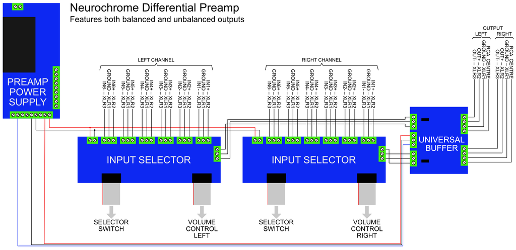
I hope this page has offered you some insight into the design tradeoffs involved in designing a high-end preamp. Should you be interested in reading more about small-signal audio design, I highly recommend Douglas Self's book on the topic. I found the chapter on the switching of audio signals particular insightful in my preamp designs.
Please Donate!
Did you find this content useful? If so, please consider making a donation by clicking the Donate button below.